Diamond cutting blade (3) for marble and stone blocks (B) - particularly defective ones, incorporating clefts (1) and inner or dead cavities (2, 4) - of the type carrying, fixed on its cutting edge (3') and suitably spaced, a plurality of diamond segments (7) meant to perform the cutting. According to the invention, the space between said diamond segments, along the blade cutting edge and at least next to the inner corners of such segments, is filled with material apt to wear more easily than the diamond segments. In a preferred embodiment, said material is in the form of inserts (8) consisting of bronze or brass parallelepiped elements fixed projecting from the blade cutting edge (3') so as to substantially fill the entire space between the diamond segments (7), the lower edge of said inserts being aligned with the lower edge of said segments to form a rectilinear cutting edge. In another embodiment, said inserts (8) are shaped as a triangle, to fill merely the space in correspondence of the inner corners of the diamond segments (7), the lower edge of said inserts being beveled in respect of the lower edge of the diamond segments to form a continuous undulated cutting edge.
DESCRIPTION
[01]
As known since many years, marble or stone blocks are cut into slabs by means of special machines called "Gang Saw " or "Frame Saw", making use of diamond tools known as "diamond blades". Such machines consist of a blade carrying frame, moved with a reciprocating motion, on which the diamond blades are mounted perfectly parallel and mutually spaced at a preset distance. The diamond blades are kept longitudinally tensioned by special tension means and laterally spaced by appropriate spacing rules.
[02]
The diamond cutting blades consist of a steel band, normally having a section of 180x3 mm and a length of about 4,0 mm. On their lower edge, forming the cutting edge, they carry small abrasive inserts called "diamond segments", suitably welded at a reciprocal distance. Diamond segments of this type are described, for example, in the EP-A-0.090.274.
[03]
The gangsaw blade carrying frame, with the blades mounted in this way, is moved not only with a longitudinal reciprocating motion, but also so as to perform a slow downward movement onto the marble block, thereby cutting it into slabs.
[04]
With the aforedescribed technique it is quite easy to convert blocks into slabs - if the blocks show no defects - using exclusively water to act as cleaning and cooling element.
[05]
If, however, the blocks show defects of shape or compactedness, especially clefts or inner cavities, this may easily cause the breakaway of the gang saw diamond segments, with consequent damage for the block and for the blades involved.
[06]
Said breakaway is normally produced by small marble or stone chips which, finding themselves inside the cavities present in the block, or breaking off from said block in correspondence of its defective parts, remain loose into said clefts or cavities, and are stuck therein with no possibility to be expelled.
[07]
When the blade or, rather, the diamond segments welded thereon get in contact with such small marble or stone chips, these may interpose themselves between the diamond segments (moving with a reciprocating motion) and, in some cases, stand in the way and form a sharp obstacle, thereby causing, through impact, the sudden breakaway of one or more segments. Normally, the number of removed segments, for an even small defective part, corresponds to the number of segments welded onto a blade section, the length of which corresponds to the length of the stroke of the reciprocating motion of the blade carrying frame through the cavities present in the block.
[08]
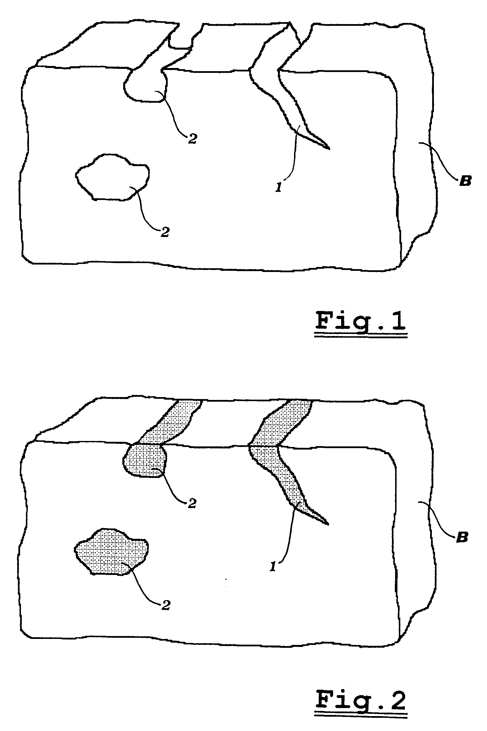
When the defect is visible from the outside of the block (see fig. 1) which has not yet been cut, the above drawback can be overcome by taking some precautions as, for example, filling with gypsum the defective part (see fig. 2). When the defect is instead hidden inside the block, since it is unforeseeable no precautionary measures can be taken.
[09]
There are blocks of natural products, such as marble, which contain true and proper holes or dead cavities, often of irregular shape and at times covered with small crystals.
[10]
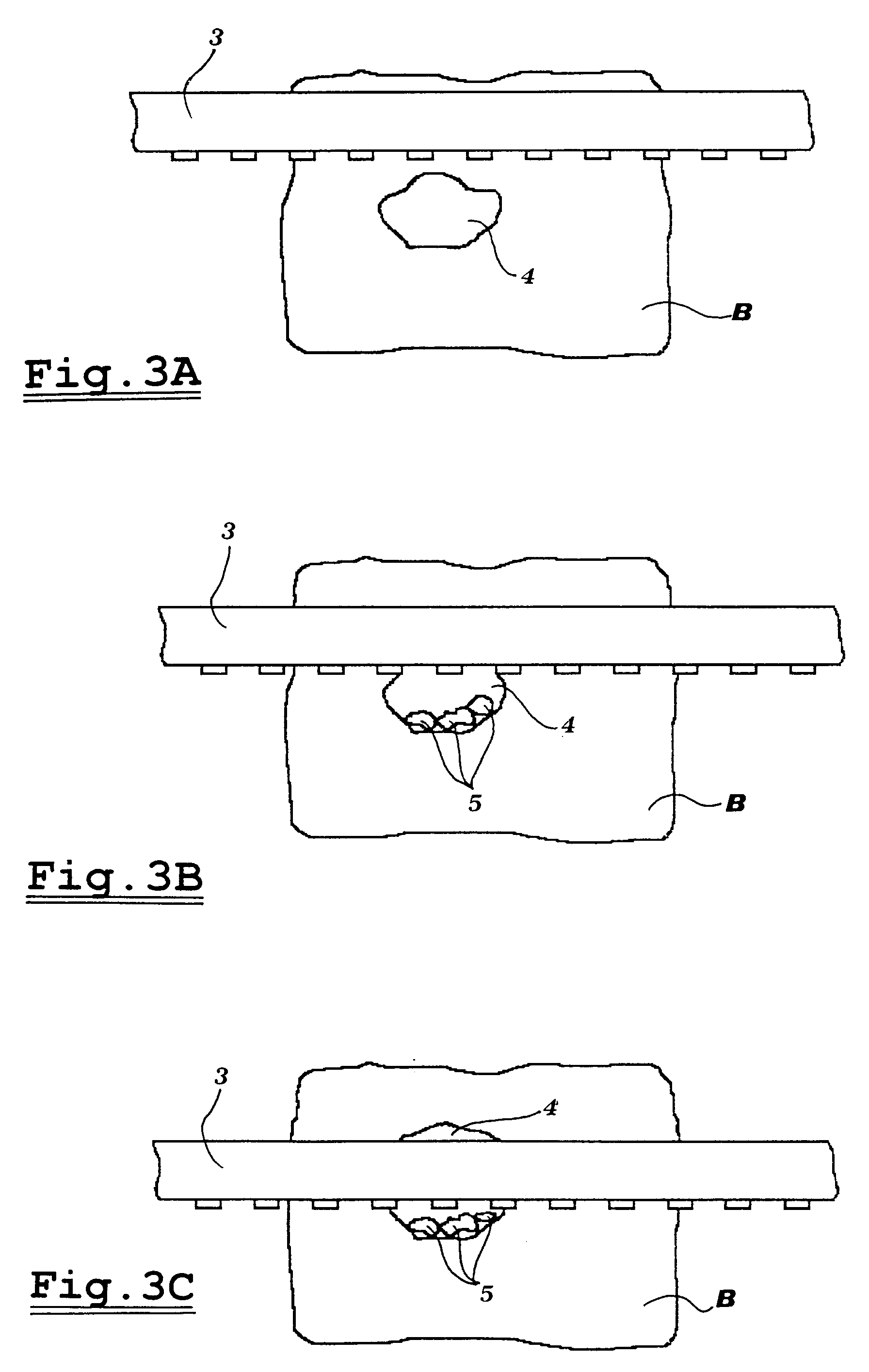
When the frame saw blade, while cutting such blocks, penetrates into said dead cavities, nothing happens at first save for the breaking off, from the top of the cavity, of small marble chips which are often harder than the actual block and are often mixed with crystals (see figs. 3). Said splinters evidently drop onto the bottom of the cavity and remain loose therein until the diamond blade, moving down, meets such splinters which, interposing themselves between the diamond segments and the cavity walls, cause the breakaway of said segments, which also end up by resting onto the bottom of the cavity.
[11]
Seldom does the operator realize at once what has happened, and the diamond blades continue their cutting operation; nonetheless, the blade sections which have been left without any segments are no longer in a condition to perform the cutting whereby, after a short while, one notices that the blade deviates from its normal cutting path and the steel band often gets ripped.
[12]
The object of the present invention is therefore a diamond blade structure which, even when working in conditions as those described heretofore, allows to prevent the drawback of the diamond segments breaking away. Said object is reached with a cutting blade of the type carrying, fixed on its cutting edge and suitably spaced, a plurality of "diamond segments" meant to perform the cutting, characterized in that the space between the diamond segments, along the cutting edge and at least next to the inner corners of such segments, is filled with material apt to wear more easily than the actual diamond segments.
[13]
According to a preferred embodiment, said material is in the form of inserts consisting of bronze or brass parallelepiped elements, fixed projecting from the cutting edge of the blade and mutually spaced by a few millimeters, so as to substantially fill the entire space between the diamond segments, the lower edge of said inserts being aligned with the lower edge of the diamond segments to form a rectilinear cutting edge.
[14]
According to a different embodiment, said inserts are shaped as a triangle so as to fill merely the space in correspondence of the inner corners of the diamond segments, the lower edge of the inserts being beveled in respect of the lower edge of the diamond segments to form a continuous undulated cutting edge.
[15]
Thanks to these arrangements, the cutting edge of the blade does not have an indented structure, but a substantially continuous rectilinear or undulated structure, so as to allow no jamming or impact between the tips of the diamond segments and the dead cavities or holes which may be present in the marble or stone blocks.
[16]
Though, according to known technique, it has already been provided to place inserts in the clefts formed into the blades for cutting stone materials, said inserts are meant for a different purpose and are apt to solve different technical problems.
[17]
For example, the GB-381229 describes a blade onto which there are applied carborundum (carbon silicide) teeth. A partial filling of soft material is provided between the teeth, to simply allow the blade to flect while being handled, thereby preventing the breakage of the carborundum teeth. In fact, the blade described in GB-381229 is not subject to the problems deriving from impacts with stone chips and splinters, since the teeth are applied on the blade at a very short mutual distance. On the other hand, at the filing date of GB-381229, the use of diamond in the cutting blades was still unknown, and thus also the problems connected thereto.
[18]
Also the FR-1.568.331 provides for clefts between the various diamond sectors forming the cutting disk. The disk blade does not normally suffer from the problems tied to the irregularities of the stone block, especially as the clefts between the diamond sectors are very narrow and do not allow the insertion of stone splinters. However, in FR-1.568.131, the clefts are filled with an easily weldable material, as silver, to prevent beats and vibrations causing noise and cutting irregularities.
[19]
Further characteristics and advantages of the cutting blade according to the present invention will anyhow be more evident from the following detailed description of some preferred embodiments thereof, given by way of example and illustrated on the accompanying drawings, in which:
Figs. 1 and 2 diagrammatically illustrate a marble block showing defects in the form of clefts and cavities and, respectively, the same block filled with gypsum according to known technique;
Figs. 3A to 3C diagrammatically illustrate a defective block while it is being cut;
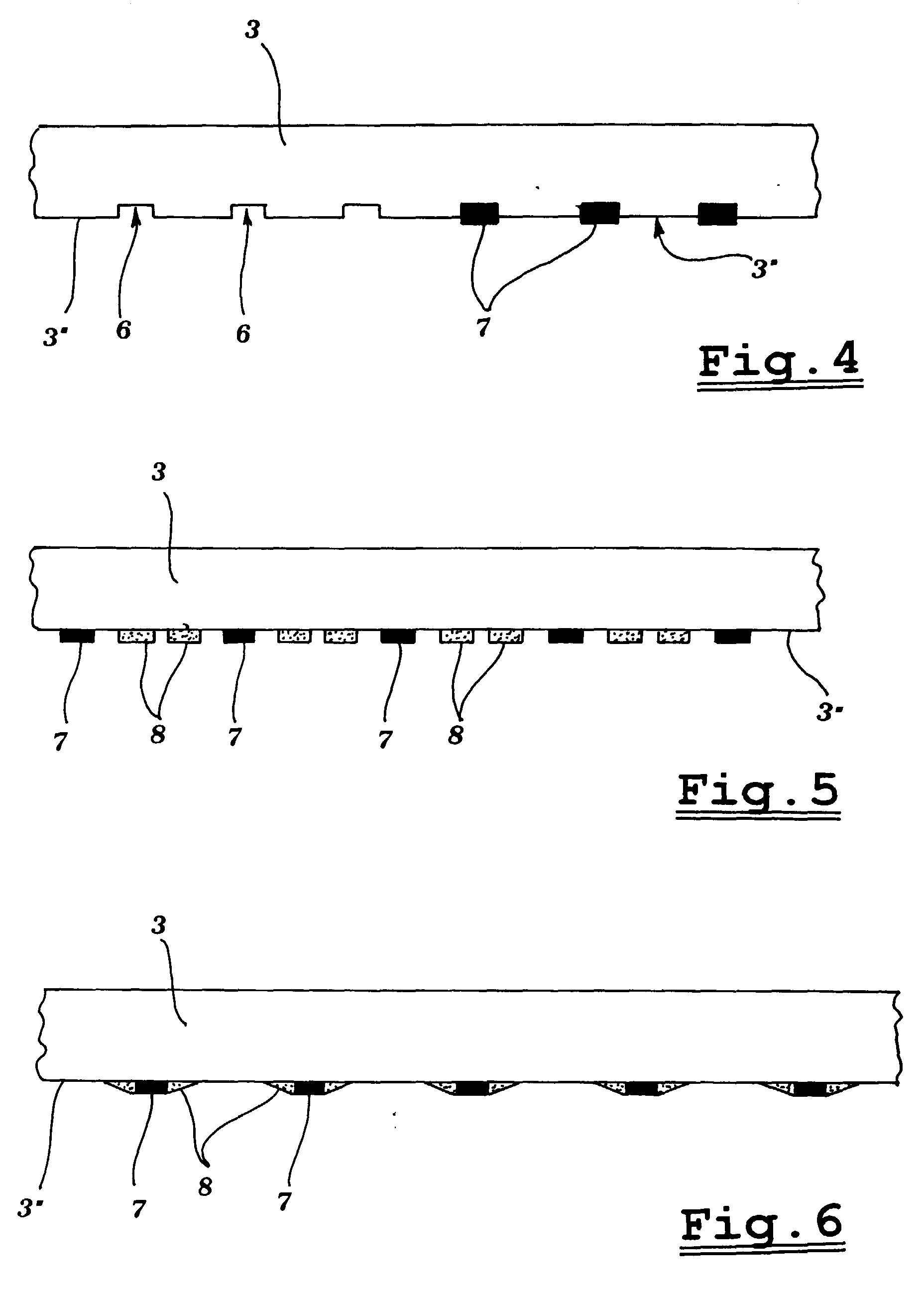
Figs. 4, 5 and 6 illustrate three different embodiments of the cutting blade according to the invention;
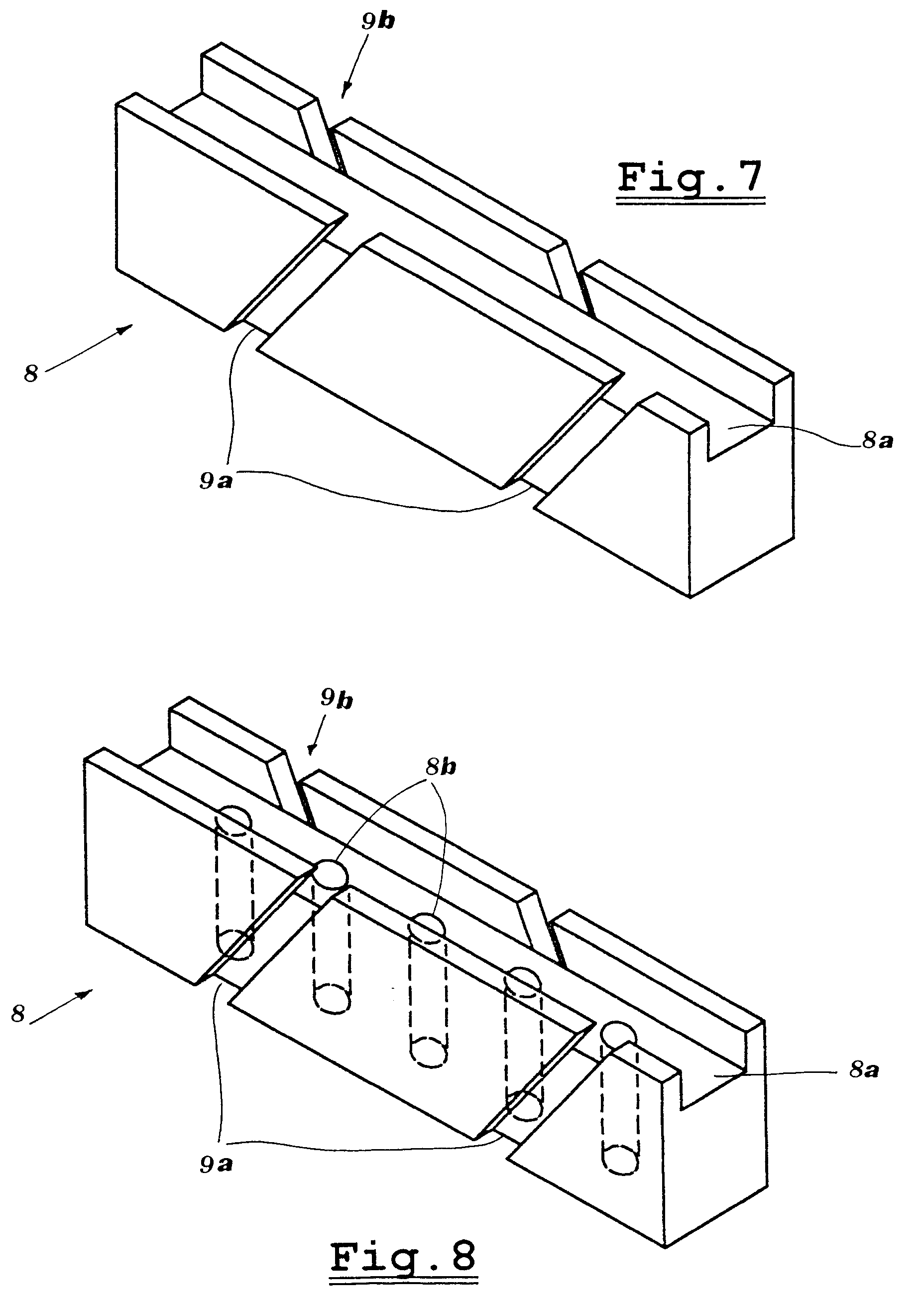
Figs. 7 and 8 illustrate two different types of wearable inserts to be fixed to the cutting blade according to the invention.
[20]
As already mentioned, when cutting marble or stone materials, one often meets with blocks B showing defects, such as clefts 1 or cavities 2 (see fig. 1), which can be noticed at once in that they open outwardly; in this case, it is then possible to stopper such clefts and cavities or fill them with gypsum, so as to avoid any cutting problems (see fig. 2).
[21]
When, viceversa, the cavities are hidden inside the block B - as the dead cavity 4 shown in figs. 3A to 3C - it is quite impossible, not only to stopper them, but even to perceive them. Thus, when the blade 3 performing the cutting reaches such a cavity (figs. 3B and 3C), it first of all produces splinters 5, which drop onto the bottom of the cavity 4 and which, when the blade 3 comes in contact therewith, create problems of impact and breakaway of the diamond segments.
[22]
According to a first quite simple embodiment of the present invention, illustrated in fig. 4, into the cutting edge 3' of the blade 3 there are formed notches 6, into which the diamond segments 7 are fixed so that their lower edge is substantially aligned with the edge 3' of the blade 3; in this way, the cutting edge is substantially rectilinear and continuous, and thus free from sharp corners which may cause impacts or jamming.
[23]
However, as the frame saw segments get worn, also the cutting edge 3' of the steel blade 3 gets worn. In fact, the drawback of this embodiment is that the steel edge of the blade, when worn, produces friction against the cutting groove, without actually performing the cutting, and thus tends to stop the blade from moving downward into the stone block.
[24]
According to the embodiment illustrated in fig. 5 - which is far more efficient - inserts 8 are fixed along the cutting edge 3' of the steel blade 3, said inserts being interposed between the diamond segments 7 and consisting of a soft and easily wearable material, such as bronze or brass.
[25]
Such inserts 8 are fixed to the steel blade by welding or glueing and their dimensions are such that a single insert, or more side-by-side inserts, can substantially fill the entire space between one diamond segment 7 and the next, leaving however small gaps apt to favour an improved circulation of the washing water inside the cutting groove. This arrangement allows to obtain blades having once more a substantially rectilinear and continuous cutting edge, namely without any wide gaps allowing to house stone chips or splinters, and thus able to cut through holes or dead cavities of any shape and size without causing the undesired and expensive problem of the breakaway of the diamond segments.
[26]
Apart from this, the soft surface of the bronze or brass inserts 8, though performing no cutting action, opposes no resistance to wear and does not hence interfere with the cutting action of the diamond segments 7. Such an arrangement has therefore proved to be really capable of solving the aforementioned problem in a practical and efficient manner.
[27]
According to the embodiment illustrated in fig. 6, the inserts 8 - instead of having a substantially rectangular shape, like those of the embodiment shown in fig. 5 - are shaped as a triangle and are fixed in correspondence of the inner corners of the diamond segments 7. The lower surface of such inserts 8 is thus oblique and forms a beveling between the lower edge 3' of the blade 3 and the lower surface of the diamond segments 7. This configuration of the inserts 8 - even though leaving some free space between the diamond segments, which could in theory house some chips or splinters - forms a continuous undulated cutting edge, apt to fully prevent any impacts against the walls of the holes or dead cavities which may be present inside the stone or marble block, or against any loose chips or splinters, and to thus prevent the breakaway of the diamond segments.
[28]
Of course, the longitudinal dimension of said triangular inserts 8 may differ from that shown in fig. 6, and it can vary - for instance, according to the type of cutting operation having to be performed by the blade - from a minimum, essential to form a beveling, to a maximum, corresponding to half of the distance between one diamond segment and the next.
[29]
Figs. 7 and 8 show, by way of example, two types of blunt and easily wearable inserts according to the present invention. Fig. 7 shows an insert 8 comprising, along its top surface, a groove 8a to center and fix said insert onto the cutting edge of the blade, and comprising, on its opposite side surfaces, oblique grooves 9a and 9b, which are preferably oblique in opposite directions, so as to create a turbulence in the washing water which settles onto the bottom of the cutting groove and thereby improve the washing action. Fig. 8 shows another type of insert 8, which also comprises a series of through holes 8b to reduce the friction on the cutting surface.
[30]
As specified heretofore, said inserts are of bronze or of brass, since these materials are, at the same time, easily wearable and easy to weld onto the edge of the steel blade. It is evident, however, that also other materials can be used, either of metal or synthetic, providing each time for suitable fixing techniques.
[31]
It is anyhow understood that the invention is not limited to the particular embodiments described and illustrated, which merely form non-limiting examples of its scope, but that many variants can be introduced, all within reach of a person skilled in the art, without thereby departing from the protection scope of the present invention.
Previous:Set diamond blade Next:How to Choose the Best Diamond Blade
Thank you for your interest in the above content, please leave us inquiry, you can expect a response within 24 hours.
Required fields are marked *
|
|
|
|